Why acceptable parts may not fit together
A drawing usually gives each important dimension a nominal value and an allowed range, or tolerance. A part near either end of that range can still meet its drawing. Trouble arises when several parts contribute to the same assembly feature: their variations can combine to change a gap, an alignment or the force needed to put the product together. A tolerance stack-up traces that combined effect.
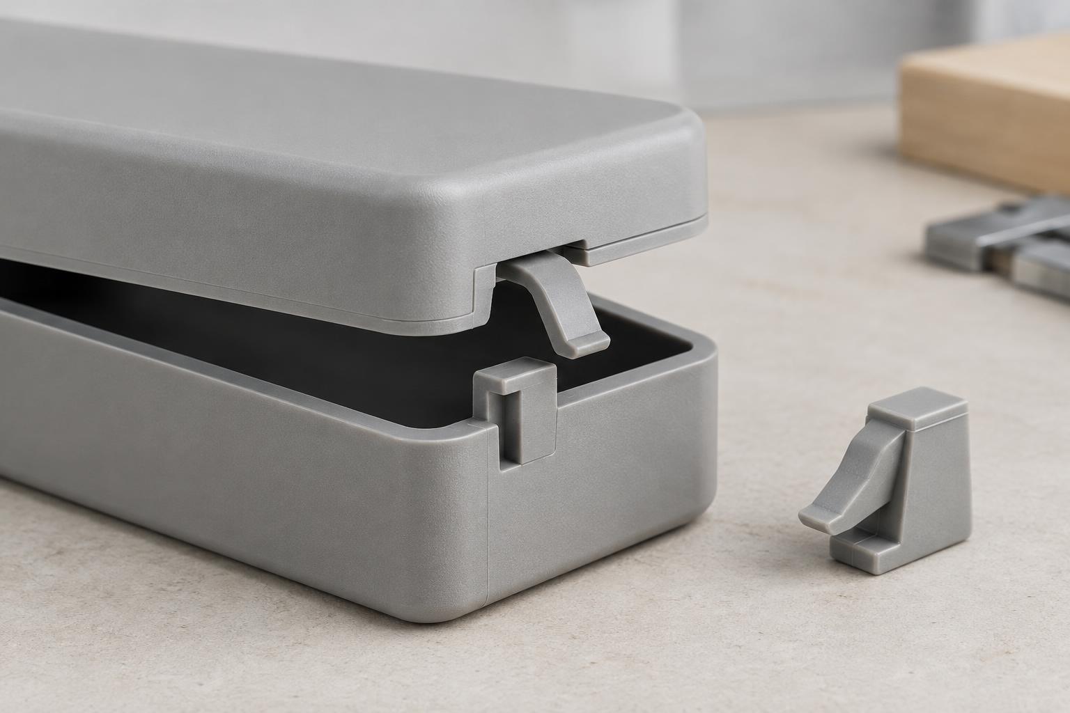
Consider a lid that must close over an internal component. The useful question is not simply whether the lid, housing and component are individually within specification. It is whether their combined dimensions leave enough clearance for the lid to close without interference, while keeping the visible gap acceptably small. Framing the problem around that functional result makes the analysis useful to designers and manufacturers alike.
Build the chain from a functional requirement
Start by naming the feature that matters: perhaps a minimum clearance, a shaft’s position relative to a bearing, or the overall height of a closed enclosure. Identify the surfaces that locate the parts in the assembled product, then follow a continuous path through the dimensions between them. Dimensions along this path form the stack. A simple sketch with arrows helps show which dimensions increase the result and which decrease it.
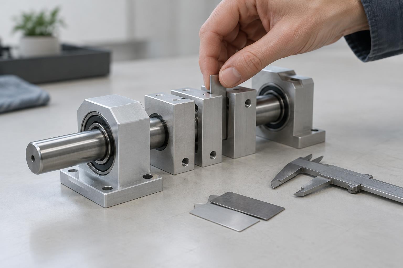
For example, imagine an opening that is 20.0 ± 0.2 mm wide. An insert occupies 12.0 ± 0.15 mm of that width, and a spacer occupies another 7.0 ± 0.1 mm. If these dimensions act along the same line, the nominal remaining clearance is 20.0 − 12.0 − 7.0 = 1.0 mm. In this chain, a wider opening increases clearance; a wider insert or spacer reduces it.
The path must reflect how the parts actually locate. A dimension measured from a convenient drawing edge may not describe the assembled position if the part seats against a different surface. Likewise, a two-dimensional sketch can miss tilt, misalignment or variation in hole location. Those effects may need their own analysis rather than being folded into a width calculation.
Check the limits with a worst-case calculation
A worst-case stack-up asks what happens if every contributing dimension reaches the allowed limit that is least favorable to the requirement. In the example, the smallest opening is 19.8 mm, while the largest insert and spacer are 12.15 mm and 7.1 mm. The minimum clearance is therefore 19.8 − 12.15 − 7.1 = 0.55 mm. Reversing those limits gives a maximum clearance of 1.45 mm.
This calculation does not predict how often either limit will occur. It checks whether the design works even when permitted variations line up unfavorably. That can be especially valuable when interference would prevent assembly or cause damage. If 0.55 mm is not enough, the team has a specific shortfall to address rather than a vague concern about fit.
A statistical approach may be useful when the extreme combination is unnecessarily restrictive. It considers how dimensions vary in production instead of treating every limit combination as equally likely. But tolerance limits alone do not reveal the underlying distributions or whether dimensions vary independently. Any statistical estimate needs justified assumptions and should be checked against production measurements when available.
Turn the result into a design decision
When a stack-up fails, tightening every tolerance is rarely the best first move. Look for the contributors that have the greatest effect on the functional result. A large tolerance in a dimension that sits directly in the chain may deserve attention; a tightly controlled dimension outside the chain may not. Changes to nominal sizes, locating surfaces or assembly order can sometimes create more room without demanding greater precision from every part.
Also ask what kinds of variation the simple chain leaves out. Parts may shift within mounting holes, flex under load or change size with temperature. Surface form and orientation can matter as much as a stated linear dimension. The relevant question is how the product behaves in its intended assembled condition, not just whether arithmetic on drawing dimensions looks favorable.
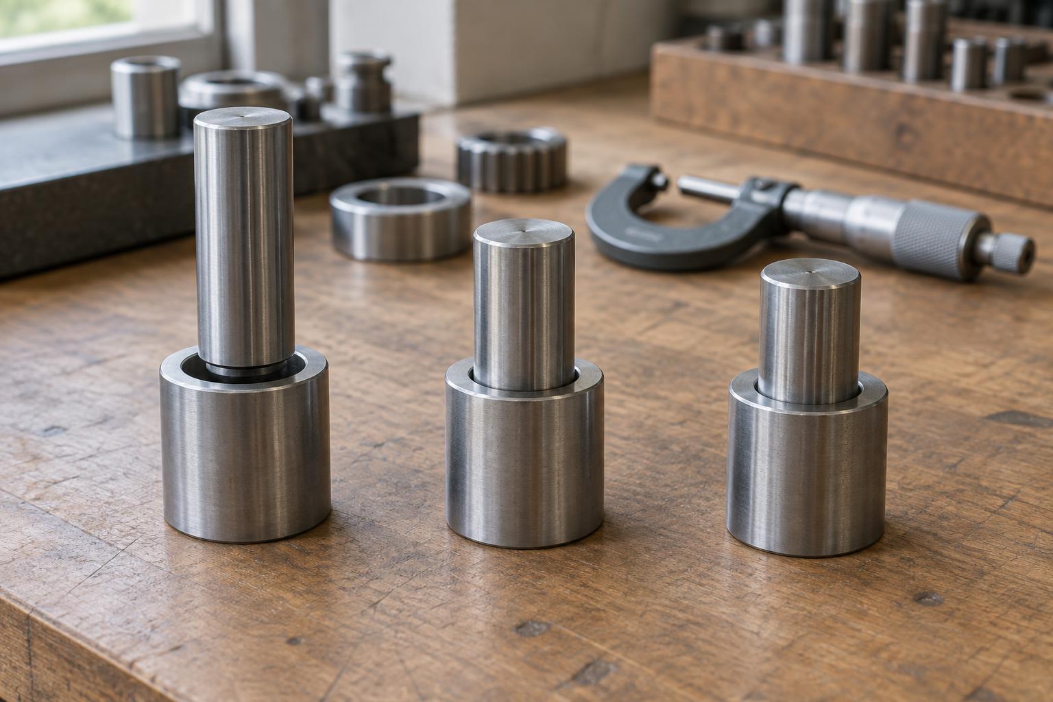
Finally, connect the calculation to an observable check. A clearance requirement might be verified with a gauge, while a moving assembly may need a functional test. Keep the stack-up sketch, assumptions and revision history with the design record so that a change to a part or its locating surface prompts a fresh review. A tolerance stack-up is most useful when it remains a living explanation of why the assembly is expected to work.