From a pulling test to a curve
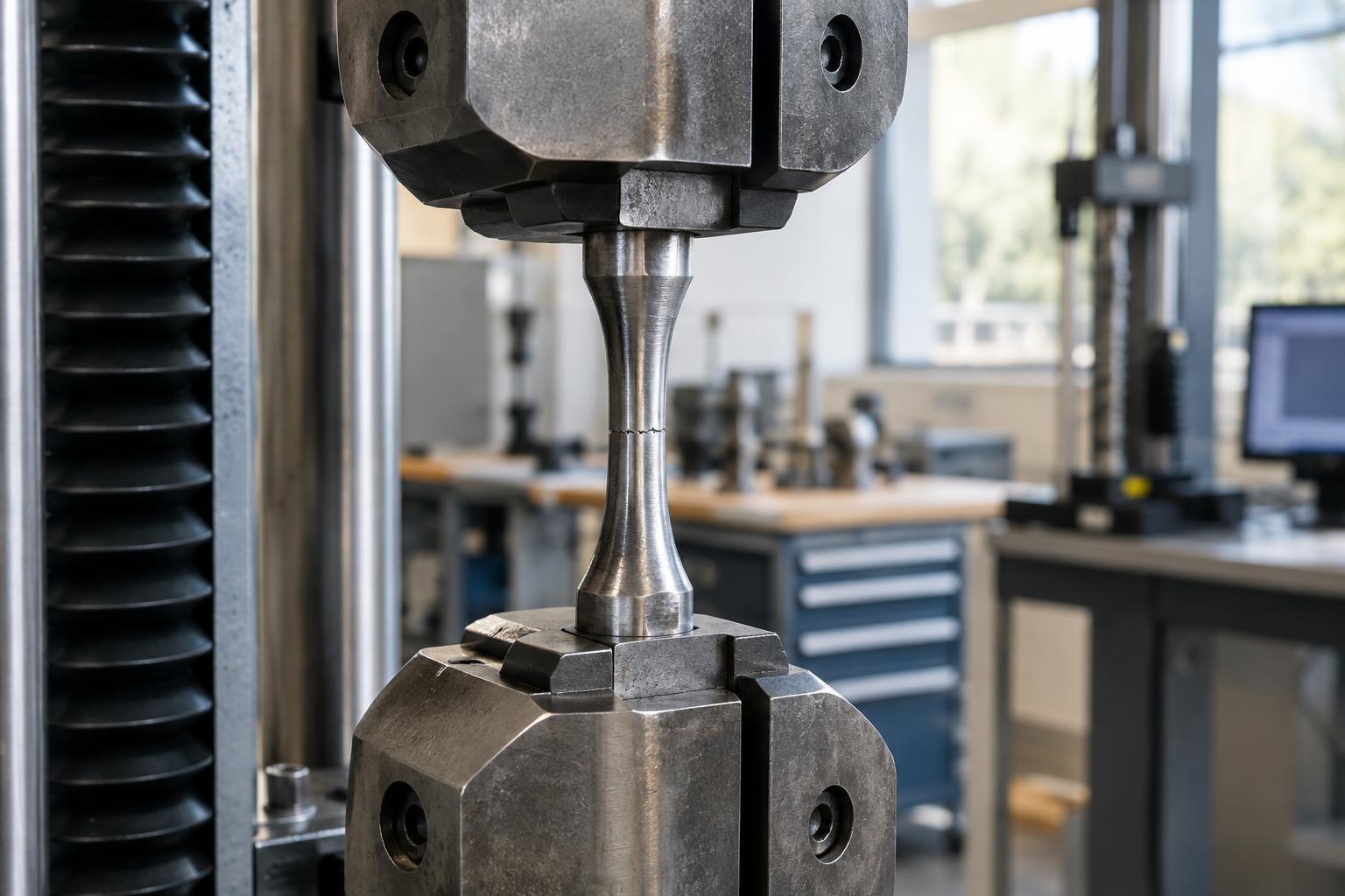
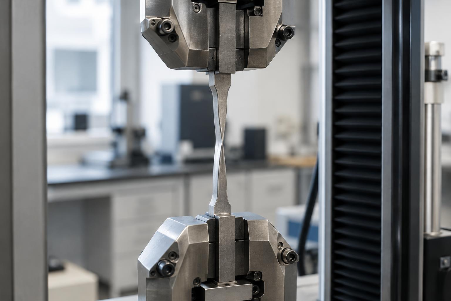
A tensile test measures how a material responds when it is pulled. A prepared specimen is gripped at both ends, and a testing machine increases the pulling force while measuring how much the specimen extends. The specimen’s shape and dimensions matter: a wide sample can carry more force than a narrow one even if both are made from the same material.
To make results more useful for comparison, force is divided by the specimen’s original cross-sectional area to calculate engineering stress. The change in length over a marked gauge length is divided by that original length to calculate engineering strain. Plotting stress against strain produces a stress–strain curve. It shows not just the largest load a specimen carried, but how it behaved throughout the pull.
The early curve: stiffness and elastic behavior
At first, many materials extend only a little as stress rises. For materials with a clearly linear elastic region, the slope of this part of the curve is the elastic modulus: a steeper slope means the material stretches less under a given stress. Stiffness is not the same as strength. A material can resist stretching yet fail at a relatively low stress, or stretch readily while carrying substantial stress.
Elastic deformation is deformation that recovers when the load is removed. A tensile curve from a single uninterrupted pull does not, by itself, show exactly how much of the extension will recover after unloading. The early response may also be curved rather than neatly linear, especially for polymers. In those cases, a single slope needs to be defined over a stated region or measured using a specified method.
Yield, peak stress and fracture
As pulling continues, some materials reach a point where permanent deformation begins. This is called yielding. Certain metals show a distinct change in the curve; others transition gradually, so a specified offset method is used to define a repeatable yield strength. Yield strength can matter when a product must keep its shape in normal use, even if it could withstand a higher stress before breaking.
The highest engineering stress reached during the test is the ultimate tensile strength. It marks the peak of the engineering stress–strain curve, not necessarily the moment of fracture. In a ductile metal specimen, a narrow region called a neck may form before the specimen breaks. Because engineering stress still uses the original cross-sectional area, the curve may fall after the peak even as the stress within the shrinking neck behaves differently.
Fracture is the end of the test, but it is not the whole story. A specimen that stretches considerably before breaking behaves differently from one that snaps after little extension. Measures such as elongation at break help describe ductility. The area under a stress–strain curve up to fracture is also related to the energy absorbed per unit original volume during the test, though its interpretation depends on how strain was measured.
Why two curves may differ
A curve describes a tested specimen under particular conditions, not every possible behavior of a material. Results can change with specimen geometry, surface condition, pulling speed and temperature. For sheet, fiber-filled plastic or other direction-dependent materials, the direction in which a specimen is cut can matter. Differences in processing may also leave two specimens of the same named material with different properties.
Measurement choices affect the curve as well. Extension measured between grips can include movement or deformation outside the gauge length, while a device measuring the gauge region more directly can give a different view of early strain. Comparing values is most useful when the test method, specimen dimensions, measurement method and conditions are stated alongside the results.
Using the curve in product development
Start with the question the part needs to answer. If it must stay dimensionally stable under load, examine elastic behavior and the relevant strain range. If permanent bending would make it unusable, look at yielding. If it may be pulled during assembly or handling, strength and elongation may both be relevant. A high ultimate tensile strength alone does not guarantee a suitable part.
Finally, connect the test to the real product. A tensile specimen experiences a controlled, mostly one-directional pull; a finished part may encounter bending, impacts, repeated loading or environmental exposure. Tensile testing provides a useful foundation for comparing materials and checking production consistency, but it works best as one piece of a broader testing plan.