What happens during a bend
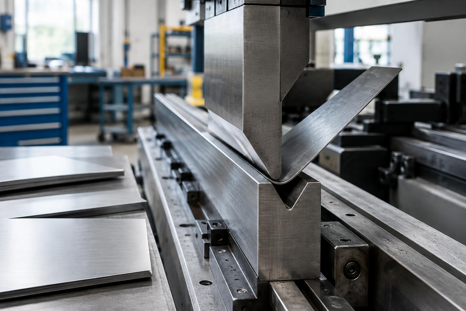
Bending turns a flat sheet into a three-dimensional part without removing material from the bend itself. In a typical press-brake operation, a punch pushes the sheet into a die. Material on the outside of the bend stretches, while material on the inside compresses. Between them is a region that changes relatively little in length, commonly represented in design calculations by a neutral axis.
A bend is defined by more than its finished angle. Sheet thickness, inside bend radius and the lengths of the straight sections all affect the size of the blank needed to make the part. The bend method and available tooling matter too: a shape that looks straightforward in a drawing may be hard to form if a short flange cannot be gripped or an existing wall collides with the machine.
Bend allowance and the flat pattern
Bend allowance is the estimated length of sheet consumed by the curved portion of a bend, measured along the neutral axis. Designers use it to work backward from the finished part to a flat pattern. One common approximation is bend allowance = bend angle in radians × (inside radius + K-factor × sheet thickness). Here, the bend angle describes the amount of turn through the curved portion, and the K-factor estimates where the neutral axis lies within the thickness.
The K-factor is not a universal material constant. It can vary with the material, thickness, bend radius and forming method. Using a convenient default may be adequate for an early concept, but it can leave a production flat pattern too long or too short. For parts that need a close fit, a shop may establish its bend data from test bends made with the intended stock and tooling.
Dimensioning conventions deserve equal care. Bend allowance, outside setback and bend deduction are related ways of describing flat length, but they are not interchangeable numbers. Before calculating a blank, establish whether the drawing dimensions run to inside surfaces, outside corners or bend tangent points. For a part with several bends, small errors at each bend can accumulate at the final edge.
Why springback changes the finished angle
When forming force is removed, some elastic deformation recovers. This springback changes the angle from the position reached under the punch; an air-bent flange, for example, may open slightly after release. The amount depends on factors including material properties, thickness, bend radius and forming method. Even sheets sold under the same general material name may not behave identically in a demanding application.
Fabricators compensate by adjusting the forming operation rather than assuming the sheet will stay exactly where the tooling pushes it. The required adjustment is best established with the actual material and process. If angle accuracy is important, specify the acceptable finished angle and a practical inspection point, then allow for a trial bend or first-part check. A nominal tool position alone does not define the finished geometry.
Design mistakes that make bending harder
A frequent mistake is placing holes, slots or cutouts too close to a bend. The nearby metal is being stretched and compressed, so an opening can distort instead of remaining round or holding its intended position. Another is omitting bend relief where a bend ends at an edge or meets a cutout. A suitable relief can reduce tearing and unwanted deformation, although its shape and size should be matched to the material and process.
Very tight inside radii can increase forming difficulty and the risk of cracking, particularly when the material has limited formability. Bend direction relative to the sheet’s rolling direction can also matter for some materials and tight bends. Other common problems include flanges shorter than the tooling can support, bend sequences that trap a part against the punch, and dimensions that demand tight tolerances across several bends without identifying which features are most important.
These issues are easiest to resolve while the part is still a drawing. Ask whether every bend can be reached in a workable sequence, whether the blank has room for reliefs and whether critical holes could be made or finished after bending if necessary. Such choices involve trade-offs in cost, accuracy and handling, so the best answer depends on the part rather than a single rule.
A practical check before releasing a design
Start with a clearly defined material and thickness, then show the intended inside radii, finished angles and critical dimensions. Build the flat pattern using bend values appropriate to the planned process, and check that cut features have sufficient clearance from bends. Review each bend in sequence, paying particular attention to short flanges and possible tooling collisions.
Finally, separate dimensions that must be controlled closely from those with room to vary. A prototype or first-article bend can reveal whether the assumed allowance and springback compensation produce the intended fit. Updating the flat pattern from that result is usually more reliable than treating an initial calculation as a guarantee.