Milling removes material in a controlled path
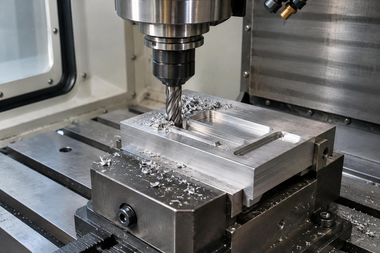
CNC milling is a machining process that shapes a workpiece by removing small pieces of material, called chips. A motor turns a cutter with one or more cutting edges. As the cutter and workpiece move relative to each other, those edges shear material away. Computer numerical control, or CNC, tells the machine where to move, how fast to feed the cutter and when to change tools.
Milling often starts with a block, plate or casting that is larger than the finished part. It can make flat faces, slots, pockets, holes and shaped surfaces. The finished geometry depends on more than the programmed outline: the cutter must be able to reach the material, and the workpiece must stay securely in place throughout the cut.
How the machine and workpiece move
On a common three-axis mill, motion is described along X and Y across the work area and Z up and down. Depending on the machine, the table, the cutter or both may move to create these relative motions. Additional rotary axes can turn or tilt a part or tool, providing access to more sides without always requiring a new setup.
Before cutting, an operator establishes a reference point so the machine can relate the program to the actual workpiece. The workpiece is then held by a vise, clamps or a purpose-made fixture. Good workholding resists cutting forces while leaving enough room for the cutter to reach its target. If a part shifts, even an accurate program may produce the wrong shape.
What different cutters do
A cutter’s shape determines which features it can produce. An end mill can cut with its sides and, when designed for it, its end. It is useful for pockets, profiles and slots. A face mill uses cutting edges across a wider diameter to machine broad, flat surfaces. Ball-nose cutters have rounded ends that can follow curved surfaces, though they may need closely spaced passes to leave a smooth result.
Cutters also differ in diameter, number of cutting edges and material. A small cutter can reach narrow features but may be less rigid than a larger one. A larger cutter may remove material efficiently yet be unable to fit into a tight internal corner. Because a round cutter cannot create a perfectly sharp inside corner by itself, designers sometimes provide corner radii or plan for another process when a sharp corner is essential.
Tool paths and cutting conditions
A tool path is the planned route the cutter follows. A part may first receive roughing cuts that remove much of the excess material, followed by lighter finishing cuts that bring surfaces closer to their intended size and appearance. The program also needs safe moves between cuts so the tool does not strike a clamp or an uncut portion of the workpiece.
Spindle speed describes how quickly the cutter rotates; feed rate describes how quickly it advances through the material. Depth and width of cut describe how much material is engaged during a pass. These choices work together with the cutter, workpiece material and machine rigidity. Pushing a cutter too hard can cause chatter, poor surfaces or tool damage, while an unsuitable light cut can also make cutting inefficient. Shops adjust conditions for the specific setup rather than relying on one setting for every job.
Chip removal matters as well. Chips left in a pocket can be cut again or interfere with the tool. Air or a suitable cutting fluid may help clear chips, and cutting fluid can also help manage heat in some operations. The appropriate method depends on the material, cutter and shop equipment.
From a program to a checked part
A typical job begins with a part design and a plan for the order of operations. The machinist chooses stock, cutters and workholding, then prepares or reviews the CNC program. After setting tool positions and the workpiece reference, the operator may run checks before allowing full cutting. These steps help catch problems that are difficult to fix once material has been removed.
Inspection connects the finished part back to its design. Dimensions, hole positions and surface features can be checked with tools suited to the required accuracy. Some parts need more than one setup because the cutter cannot reach every surface from a single direction. Each repositioning adds a chance for alignment error, so the sequence of setups is part of the manufacturing plan.
CNC milling is valued for its ability to make varied shapes through controlled, repeatable motion. It is not simply a matter of sending a drawing to a machine: accessible geometry, secure workholding, appropriate cutting conditions and careful checks all help turn the programmed path into a usable part.