What happens during CNC turning
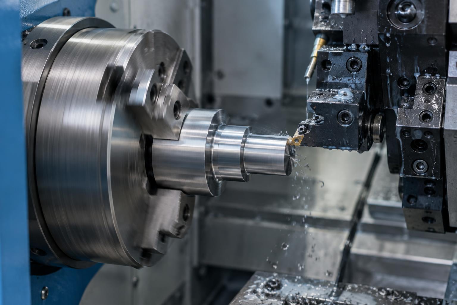
A CNC lathe makes parts by spinning a workpiece while a cutting tool removes material. Computer numerical control, or CNC, directs the tool along a programmed path. In a basic turning operation, the tool travels along the length of the rotating stock to reduce its diameter. It can also move toward the center to cut an end face flat. This combination makes the lathe well suited to parts built around a central axis, such as pins, shafts, spacers and bushings.
The starting material is often round bar, although a casting or a previously machined piece can also be turned. Unlike a typical milling machine, where the cutting tool spins against a held workpiece, the main cutting motion on a lathe comes from the workpiece rotating. Some CNC lathes also have powered tools for features such as cross-holes, but those capabilities depend on the machine.
From stock to a secure setup
Before cutting begins, the operator chooses how to hold the stock and how much material to leave for machining. A chuck grips the workpiece with jaws; a collet grips suitable stock around its circumference. The choice depends on the part’s shape, size and required access. Enough material must project from the holder for the tool to reach the intended features, but a long unsupported projection can flex or vibrate during cutting.
The setup also establishes where the program considers its reference positions to be. Tools are measured so the control can account for their locations, and the first cuts may be checked before a full batch runs. For a long shaft, support from a tailstock or another support device may help limit deflection. If both ends need machining, the part may need to be removed and held again, making the second setup an important part of the process plan.
The features a lathe can produce
Straight turning creates a consistent outside diameter. Facing squares an end, while taper turning changes the diameter gradually along the part. A tool can cut grooves or a thread, and a parting tool can separate a completed piece from bar stock. For internal features, a drill can start a hole along the rotational axis; a boring tool can then enlarge or refine it. These operations can be combined to make a component with several steps, shoulders and recesses.
A drawing may look simple because most of its features are circular, yet their order matters. For example, removing too much material early can make a slender section less rigid for later cuts. A narrow groove may call for a different tool from a broad outside surface. Features hidden behind a shoulder, or too close to the workholder, can also limit tool access. Thinking about how the tool reaches each surface helps distinguish a turnable design from one that needs another setup or process.
What controls accuracy and surface finish
A program specifies cutting paths and conditions such as spindle speed, feed and depth of cut. The material, tool geometry and workholding affect which conditions are practical. Heavy cuts can remove stock efficiently, while lighter finishing cuts can help produce the final size and surface. Chips must be managed so they do not interfere with the tool or scratch the part; cutting fluid may be used where appropriate for the material and operation.
Even with a repeatable program, parts are not automatically identical. Tools wear, stock can vary, and heat or cutting forces can change how a part behaves. Operators therefore inspect important dimensions and may adjust tool offsets to keep the process on target. A specified diameter, a smooth surface and a low amount of runout are different requirements, so each needs a suitable check. The achievable result depends on the complete setup, not just the precision of the machine’s movements.
Designing and checking a turned part
For someone specifying a turned component, the most useful starting point is to identify which surfaces must fit or move against other parts. Give those surfaces clear dimensions and tolerances, while avoiding unnecessarily tight requirements elsewhere. A small edge break can make a part easier to handle, but it should be defined when its size matters. Deep, narrow holes and very thin sections may be possible, yet they can complicate tooling and inspection.
Inspection might use calipers or micrometers for accessible diameters, gauges for certain holes or threads, and other methods for features that are difficult to reach. The choice should match what the drawing actually requires. CNC turning is most effective when the design, holding method, cutting sequence and checks are considered together: the aim is not merely to make a round shape, but to make the required features reliably and verify that they meet their purpose.